After you’ve deployed a Workload Domain, or a new Cluster, you may want to deploy an NSX Edge-Cluster. You should be aware that there are now two methods you can use to get traffic into, and out of your SDN when using VPCs. These are called Centralized and Distributed Transit Gateway. You can read more about the pros and cons of distributed and centralized by clicking the links.
Regardless if you’ve chosen Centralized, or Distributed, you can now configure/deploy this from vCenter, or NSX. In VCF9.0.1.0, it is a requirement to use Centralized if you want to use VCF Automation – AllApps (Multi Tenancy).
Before we begin to deploy Edge-Nodes, they require a Management Network for their Management Interface. VCF has created this automatically in your Management Domain, but not in your Workload Domain since there’s no vCenter, NSX Managers etc there.
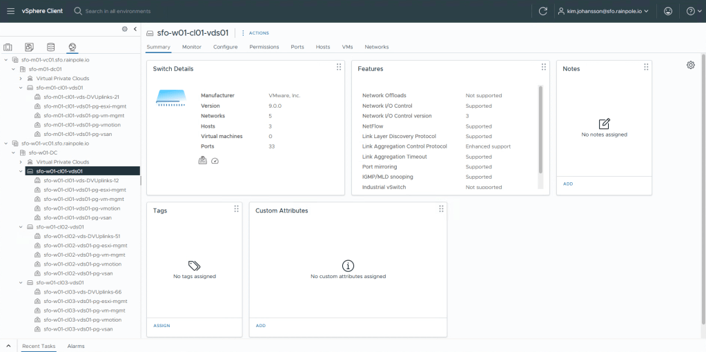
Navigate to the Network tab, and create a port-group on the VDS, or in my case, 3 VDS and create a management port-group.
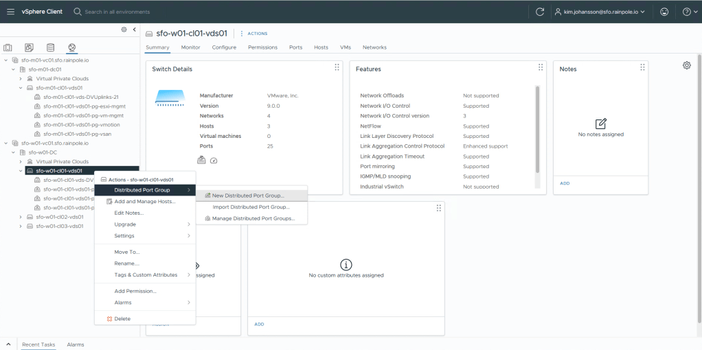
I now have 3 port-groups configured for my “vm-mgmt”.
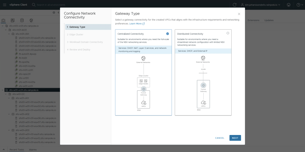
To deploy a Centralized Topology, highlight your vCenter, click the Networks tab in the top menu, then Network Connectivity below it. Now click Configure Network Connectivity to fire of the new wizard.

For now, since only Centralized is supported by VCF-A, i’ll select Centralized Connectivity, then Next.
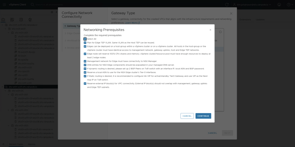
All the pre-reqs and inputs required can be found in the Planning and Preparation document under the yellow tab labeled VI Workload Domain under the header Create an NSX Edge Cluster. Check the Select All, and then click Continue.
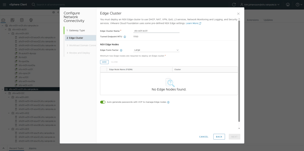
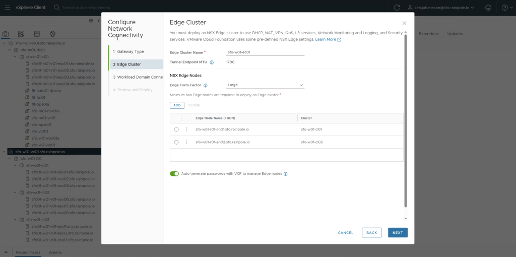
Enter the name of your edge cluster, and importantly select at least Large form factor!
This is because VCF-A, will setup a large amount of load balancer sessions, and load balancing for kubernetes is only supported on at least Large size!
Now we need to add two edge-nodes, click Add.
Configure the inputs according to your Planning and Preparation document.
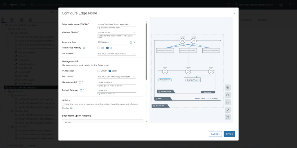
When your done, click Apply.
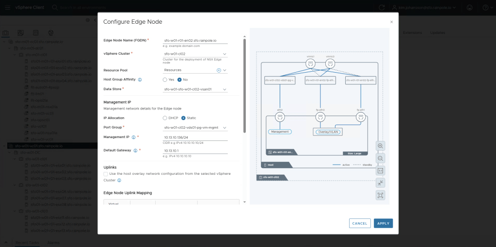
Now we’re going to do exactly the same for the second node. Since i have multiple clusters, i’m going to place my second node in Cluster 02, just to get higher availability.
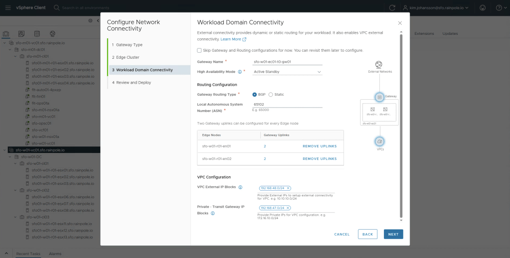
After adding the second node, you should now be done with configuration of the actual nodes, now we need to configure the peering. Click Next.
An import note in the next step is that you need to use Active Standby, this is because we don’t use T1s with VCF-A, so the load balancers will be created and run on the T0 instance. The VPC External IP Blocks, and Private – Transit Gateway IP Blocks should be two ip-ranges that are not currently used in your company, and wont be used by Organisations that you would create in VCF-A.
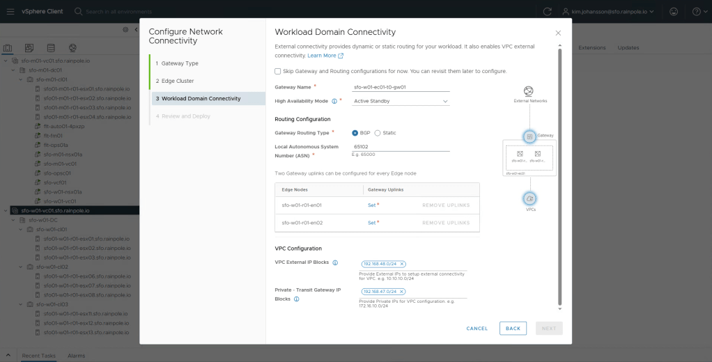
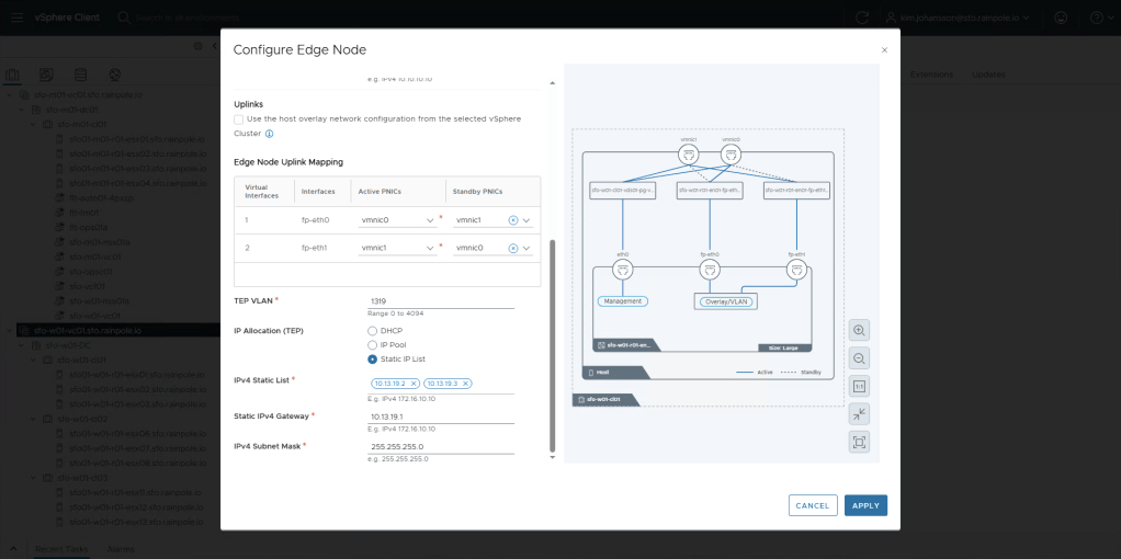
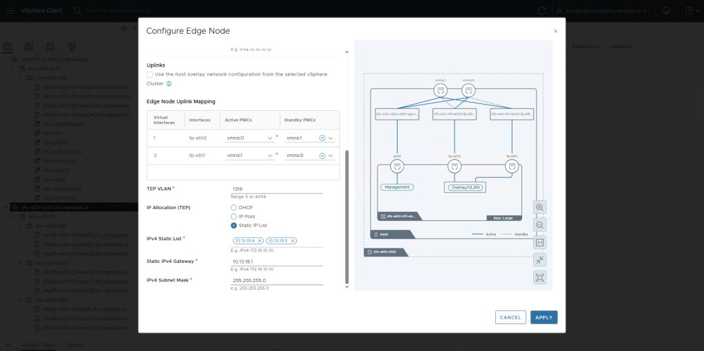
For each of the nodes, we now need to configure Uplinks, click Set, next to each edge-node.
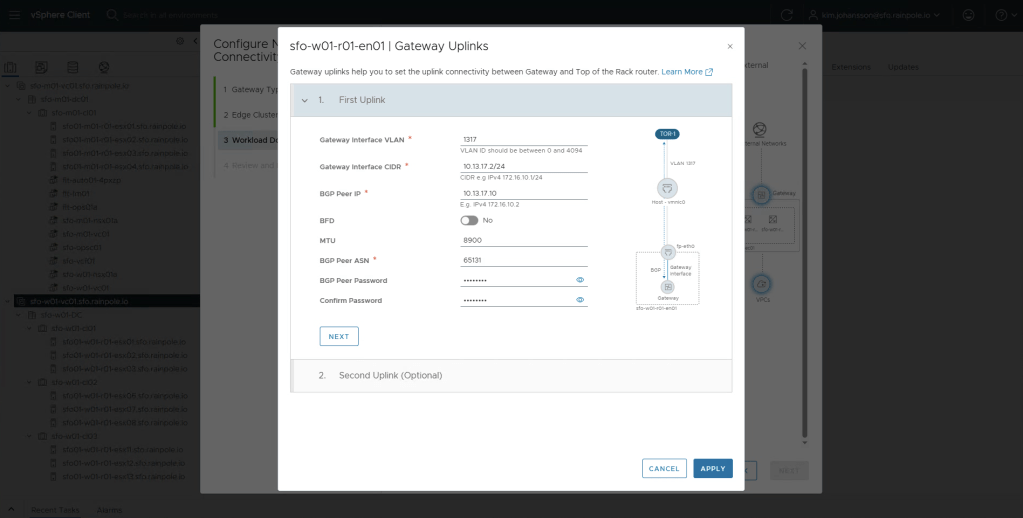
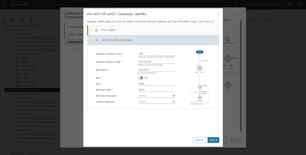

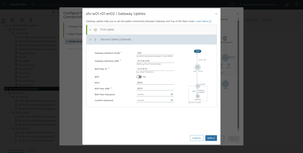
You should now have two very similar configured edge-nodes, the only things differing would be the unique uplink ip addresses provided to the edge-nodes. My MTU looks a bit odd, but it’s because this is a nested environment. There’s not really any need to use anything over 1500 MTU for the uplinks, only the TEP networks really require 1700 MTU. Click Next.
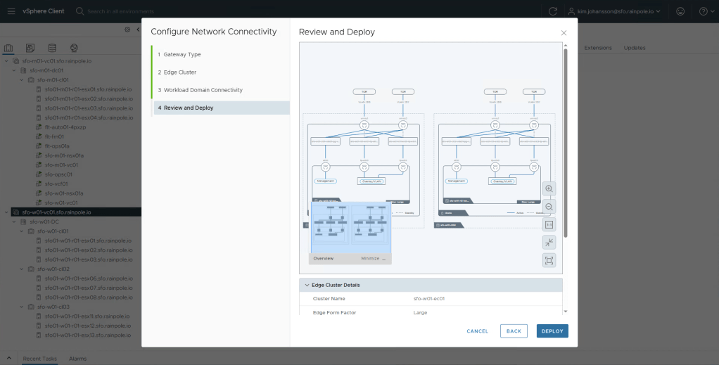
Tripple check everything looks good, and click Deploy.
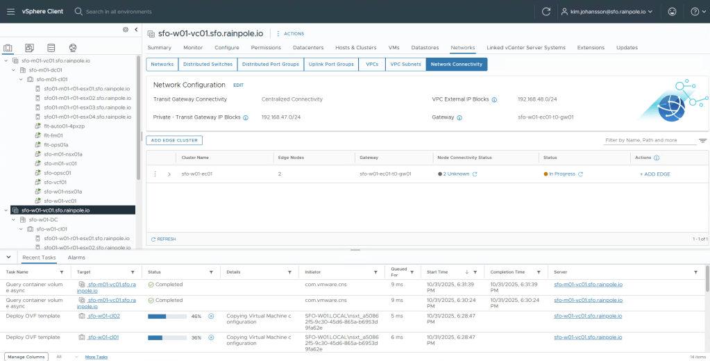
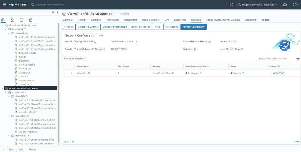
Now just monitor until the Status turns green.
Tada!
So we now have a network setup where you can either go ahead and manually start creating overlay segments, or start configuring VCF-A to allow people to use self service!
